McBean is a fast and enthusiastic worker. As far as I've checked, the update entails a compression chamber option for tapped horns.
Hornresp download site.
Sunday, March 30, 2008
Saturday, March 29, 2008
Kolbrek on horn theory, an introduction
The audioXpress magazine has a couple of articles out, an introduction to horn theory by Bjørn Kolbrek. This introduction has a more theoretical approach than the papers bij Bruce Edgar in Speakerbuilder magazine. You can download these files at:
Part 1
Part 2
Part 1
Part 2
Tuesday, March 25, 2008
Hornresp update: version 18.00
David has put more options in the tapped horn wizard. It is possible to shift driver position with a scroll bar and see the frequency response chart change in real-time. This makes it much easier and quicker to find the right driver position. A great update!
Find it here.
Find it here.
Monday, March 24, 2008
Schmacks Sub in Sketch Up
This is just a quick one with some pictures.
Before I made this horn, I made a Sketch Up model to see where all the panels went. When I started the model, I wasn't sure yet, but when I realised how few panels there are and that most are pretty easy to cut and position, I decided to go ahead. Here are two depictions of the interior, that make it easier to visualise the internals of this horn:


Next is what I believe is the standard, intended placement of this horn, in a corner.

Finally, this is the way I wanted to put it in my room. You can see it's put on its side. This makes no difference to the functioning of the horn, as the boundary loading is exactly the same. The footprint is a lot smaller though, so this positioning takes up less space.

The corner Schmackshorn, a subwoofer
A familiar classic backloaded horn, is the Schmackshorn. While I can't precisely trace back the maker of the original design, I do know that the most widely known versions are from the Klinger book of loudspeaker designs. I mentioned this book earlier in reference to the Dinohorn, anyone interested in European horn DIY will come across it a lot. I know of at least two other derivations, which take the original design elements a step further. One is the Isophon version, with lots of reflectors, the other, is the Side Vivace, an adaptation for Lowther and other fullrange drivers, which uses helmholzresonators to smooth response.
The Schmackshorn is famous for being a fairly large and uncompromised horn. Its size enables it to have a low and efficient bass response. This is something that many fullrange drivers need help with, so the Schmacks was often used with such drive units. Combinations by Philips/Norelco, Coral, Lowther and Fostex are known, probably many more. An added trait of these horns, of larger horns in general, is that their hornmouth/radiating surface is very large and therefore closer to the size of a natural low frequency soundwave. Most backloaded horns have fairly small mouths. While small-mouthed horns can sound good, large mouths generally tend to help a lot.

The Schmackshorn is famous for being a fairly large and uncompromised horn. Its size enables it to have a low and efficient bass response. This is something that many fullrange drivers need help with, so the Schmacks was often used with such drive units. Combinations by Philips/Norelco, Coral, Lowther and Fostex are known, probably many more. An added trait of these horns, of larger horns in general, is that their hornmouth/radiating surface is very large and therefore closer to the size of a natural low frequency soundwave. Most backloaded horns have fairly small mouths. While small-mouthed horns can sound good, large mouths generally tend to help a lot.
A fascinating combination of both (large mouth and lots of driver surface), is this version of the Schmackshorn. Click image for a higher resolution. This comes from an Italian website and there are more Schmacks-plans there.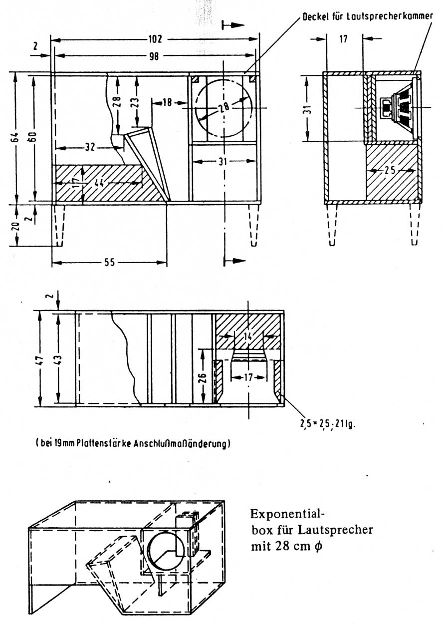
It is a design for a 12 inch driver. It was also featured in the loudspeakerbook by Klinger. This is another backloaded horn, with a rather simplified but clearly Schmacks-style folding. As far as I know, this is a bottom-firing corner horn. The only illustration (drawing, not a photo) of an application I saw, was two of these firing in corners. I haven't found more details on placement. I think it is very likely that it is a corner horn, or is suitable for corner placement, based on length and mouthsize calculations.
The Schmackshorns are "old-style" horns, which means they are designed around a number of standard rules of classic horn theory (the type by Olson). These horns generally had a quarter wavelength of the lowest intended frequency, and a mouthsize appropriately reduced for room placement (1/8th for corner placement, 1/4th for wall placement, etc. etc.).
After measuring the internal length of this horn in a few different ways, I always end up with a hornlength of around 280-290 cm. The quarter wavelength of a 30 Hz, is 285 cm, so I have decided that his horn is very likely a 30 Hz horn. Reverse engineering the mouthsize is somewhat harder, as its bottom firing. A general rule of thumb I have seen for bottom firing horn mouths, is that the final mouth size is about two times the mouth coming out of the cabinet. However, I have also seen suggestions of 1.6x to 3x as large. Also, making the final hornmouth smaller is a trick to modify/repair the acoustic impedance of the horn, so relating the mouthsize to a cut-off frequency is tricky. I come up with estimates between 6,000 and 9,000 cm^2, of which 9,000 cm^2 would be expected with a 30 Hz flare rate (throat size is 400 cm^2). Pretty good approximation, if you ask me.
Simulation in Hornresp shows that the difference is rather insignificant, leading to only minor differences in the simulated response. These are most likely smaller than the accuracy of Hornresp, so from here on, I consider this to be a 30 Hz horn, with a mouth of roughly 9,000 cm^2. Considering I model this in a corner, and considering some designed-in extension of the horn using room boundaries, this is not unlikely at all.
Furthermore, we can see a cancellation dip around 100 Hz, which is where the directly radiated sound interferes with the horn sound. It is interesting to note the cabinet design has parallel surfaces between the floor and the (inside) top of the cabinet. The distance between them is about a quarter wavelength of 100 Hz. A possible occurring standing wave will attenuate the horn sound at 100 Hz and the cancellation dip may be greatly reduced by this. This is a feature also known from the Olson backloaded horn and a suspected factor of succes in the Fostex recommended enclosures. By either placing these standing waves at a single frequency or spread out over a larger area, response anomalies can be controlled acoustically. A very interesting feature of this design. I have no measurements of the horn, so I don't know if it works the way I see it.
Now, I used to have one and I liked it, but threw it out when I moved to a new home. I regret that now. It had a really nice low bass range. It was a bit messy in the crossover region to midrange horns (220 Hz), but then again I had no measurements and therefore the crossover was messy. I'd really like to build one or two again and do measurements, a good crossover, apply it in an appropriate range. It really deserves it.
(Note: I posted this a day or two, three ago, but because I started writing on this post earlier in March, it was posted way below. Apparently you give it a date and time of posting when you start the draft. I moved it back up, since it's the most recent message. )
Sunday, March 16, 2008
Lowther Voigt Museum
Here's a really nice link!
Paul Voigt was the developer of what we now know as the Lowther drive units. These are developed a bit further, but much of their design is as it was in the thirties. While there are other strategies for fullrange drivers with high efficiency (ie smaller or larger diameter, without whizzer cone, different materials, different suspension characteristics), the Lowther school is still highly respected and led to other drivers following a similar strategy. AER and Fostex come to kind, Feastrex as well.
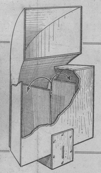
Paul Voigt initially put these drivers in large frontloaded horns. There were large, ready made, furniture grade cabinets, but also a DIY kit to be built from plans, pictured here. Whether he designed the drivers to be placed in horns, or designed the horns to make the drivers work, I don't know, but the end result is the same. This type of drivers has a response curve and a suspension type that works best in a frontloaded horn. By this, I mean that there is more treble and a general decline in lower frequency response. The horn boosts the lower frequencies and restores balance. The horn also reduces distortion, damps resonances in the driver, and gives that horn flavour that counts (even if only psychologically). In principal, you can apply this to any low Qts driver with a tilted frequency response.
Modern examples of large horns for these drivers, are the Oris range of horns by BD-Design. I have used Lowthers in "official" backloaded horn designs and was quite happy with the results, but after hearing a full-tilt Oris system at the BD-Design audition room, I started making fronthorns for my Lowthers as well. The positive effect of front hornloading was strong, expect a more dynamic, relaxed and controlled sound.
Back to the Lowther Voigt Museum. Basic horn formulae haven't changed much since the days of Paul Voigt, the application of these rules has. Nevertheless, it is very interesting to see these old designs and meditate on the creative use of knowledge of the time. Even if you don't build a Home Constructor Horn, it is noteworthy that Voigt obviously saw an advantage to using a large frontloaded horn, as opposed to say a backloaded horn, or use a smaller fronthorn to go with the TQWT/resonant pipe. Apart from this, it's just cool to see some pieces of historical significane.
The website offers some history of the company and persons, it gives pictures and descriptions of products and. apparently, the museum also sells copies of brochures and plans.
http://www.lowthervoigtmuseum.org.uk/index.html
Paul Voigt was the developer of what we now know as the Lowther drive units. These are developed a bit further, but much of their design is as it was in the thirties. While there are other strategies for fullrange drivers with high efficiency (ie smaller or larger diameter, without whizzer cone, different materials, different suspension characteristics), the Lowther school is still highly respected and led to other drivers following a similar strategy. AER and Fostex come to kind, Feastrex as well.
Paul Voigt initially put these drivers in large frontloaded horns. There were large, ready made, furniture grade cabinets, but also a DIY kit to be built from plans, pictured here. Whether he designed the drivers to be placed in horns, or designed the horns to make the drivers work, I don't know, but the end result is the same. This type of drivers has a response curve and a suspension type that works best in a frontloaded horn. By this, I mean that there is more treble and a general decline in lower frequency response. The horn boosts the lower frequencies and restores balance. The horn also reduces distortion, damps resonances in the driver, and gives that horn flavour that counts (even if only psychologically). In principal, you can apply this to any low Qts driver with a tilted frequency response.
Modern examples of large horns for these drivers, are the Oris range of horns by BD-Design. I have used Lowthers in "official" backloaded horn designs and was quite happy with the results, but after hearing a full-tilt Oris system at the BD-Design audition room, I started making fronthorns for my Lowthers as well. The positive effect of front hornloading was strong, expect a more dynamic, relaxed and controlled sound.
Back to the Lowther Voigt Museum. Basic horn formulae haven't changed much since the days of Paul Voigt, the application of these rules has. Nevertheless, it is very interesting to see these old designs and meditate on the creative use of knowledge of the time. Even if you don't build a Home Constructor Horn, it is noteworthy that Voigt obviously saw an advantage to using a large frontloaded horn, as opposed to say a backloaded horn, or use a smaller fronthorn to go with the TQWT/resonant pipe. Apart from this, it's just cool to see some pieces of historical significane.
The website offers some history of the company and persons, it gives pictures and descriptions of products and. apparently, the museum also sells copies of brochures and plans.
http://www.lowthervoigtmuseum.org.uk/index.html
Tuesday, March 11, 2008
Collaborative Tapped Horn Project
Posting here has been low, but there continues to be a constant flow of hits and views to this magazine. There are loads of people interested in hornloudspeakers online and they clearly want more stuff to read. This, I can provide, through a bulky link...
By now, a lot of horn enthusiasts will be familiar with the Tapped Horns of Tom Danley. In tapped horns, the driver is placed in such a way, that both front and rear are inside the hornpath and contributing to the final frequency response. www.diyaudio.com is hosting a thread by a number of DIY-ers, who have been reverse and forward engineering the tapped horns. Tom Danley even pops round to offer advice and hints!
This entire thread is interesting reading material. With the aid of hornresp and some background knowledge, a functional tapped horns is easily designed and constructed (think folded TQWT and you're 95% there). Those who have tried it, are generally over the moon.
Here is the link, knock yourself out with some excellent, innovative, exciting and yet accessible reading material. I start on page 1, the thread has grown to 136 pages by the time I am posting this...
http://www.diyaudio.com/forums/showthread.php?s=b42dfd69fb368c5249d462678eba5362&threadid=97674&perpage=10&pagenumber=1
Subscribe to:
Posts (Atom)